1. 引言
分形结构广泛地存在于天然的或人工的多孔材料当中,如石灰、土壤、岩石、陶瓷等 [1] [2] [3] [4]。基于分形几何,人们得以采用迭代方法模拟多孔材料的复杂结构 [5]。相较普通多孔材料,水泥基材料具有更为复杂的多孔结构,其孔隙尺寸通常涵盖从纳米(nm)到微米(μm)数个量级 [6]。研究表明,水泥基材料的多孔结构同样具有分形特征。例如,Lange等通过背散射电子扫描电镜(Backscattered electron-scanning electron microscope, BSE-SEM)图片分析技术研究孔隙尺度为0.2~2 μm范围内的分形特征,认为硬化水泥浆中存在孔隙表面分形(Pore surface fractal),也即是孔隙–固相界面分形(Pore-solid interface fractal),其维数大约为1.25且不具有尺度依赖性 [7];Winslow等通过小角度X射线散射技术(Small-angle X-ray scattering, SAXS)研究孔隙尺度为3~150 nm范围内的分形特征,认为硬化水泥浆中可能存在两种不同的分形模式,即固相分形(Solid mass fractal)和孔隙–固相界面分形,其维数为2~3且具有尺度依赖性 [8];Ji等通过压汞实验(Mercury intrusion porosimetry, MIP)研究孔隙尺度为13~34 nm和44~5625 nm范围内的分形特征,认为硬化水泥浆存在着孔隙分形(Pore mass fractal),其维数分别为0.98和2.98且具有尺度依赖性 [9];同样利用压汞实验,Zeng等认为硬化水泥浆在孔隙尺度分别为10~60 nm和3.75~5 μm的范围内存在孔隙–固相界面分形,其维数为2.59~2.96且具有尺度依赖性 [10]。
当前人们关于水泥基材料多孔结构分形特征的认识还存在一定的模糊性。具体而言,一:水泥基材料的分形模式究竟是属于孔隙分形、孔隙–固相界面分形还是固相分形;二:水泥基材料的分形结构是否具有尺度依赖性。如果不能较好的厘清这两点,对于使用分形几何方法来描述水泥基材料多孔结构的可行性势必受到影响。
2. 实验
如表1所示,三组不同水泥基材料体系用于测试分析,即普通水泥浆(Portland cement paste, OCP),矿渣水泥浆(Portland cement-slag paste, BCP),石灰水泥浆(Portland cement-calcite filler paste, LCP),其水胶比和龄期一致为0.45和60天。成型后,水泥浆试块在饱和Ca(OH)2溶液中养护,温度为20˚C ± 1˚C。养护后,水泥浆试块切成小块放入烘箱干燥。压汞实验的结果如图1所示,每条曲线为三次平行测试的平均值。通过Laplace方程确定施加压力P与孔隙直径d的关系如下
(1)
是水银的表面张力,θ是水银和孔隙表面的接触角。本文
和θ分别取为0.48 N/m和140˚ [11]。被测样品的孔隙尺寸分布(Pore size distribution, PSD)采用半对数坐标系,即dV/dlogdvs. logd。如图2所示,三组水泥浆样品孔隙尺寸大都在100 nm以下,即logd< 2。矿渣水泥浆的孔隙分布集中于0.5 < logd< 1.5。普通水泥浆和石灰水泥浆的孔隙分布集中于1 < logd< 2。究其原因,由于Ca(OH)2溶液养护的作用,矿渣水泥浆中矿渣组分的水化反应更为充分,不但降低了整体孔隙率而且细化了孔隙结构。

Table 1. Mix proportion of cement pastes
表1. 不同配合比水泥浆样品
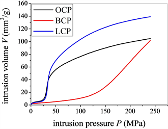
Figure 1. Porosimetric data of cement pastes
图1. 水泥浆压汞测试曲线
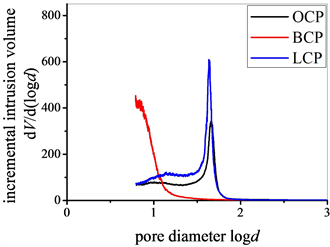
Figure 2. Pore size distribution of cement pastes
图2. 水泥浆孔隙分布曲线
3. 分形模式
当前主要有三种方法讨论水泥基材料多孔结构的分形特征,包括Ji方法 [9],Neimark方法 [12],Usteri方法 [13]。其分别对应三种分形模式,即孔隙分形,孔隙–固相界面分形,固相分形。
Ji等定义变量V*表示在压汞实验中的反向累计压入量如下
(2)
dmin表示最小孔隙尺寸。如果V*和孔隙尺寸d满足式(3),则属于孔隙分形。
(3)
DPM表示相应的孔隙分形维数。
按照Neimark方法,孔隙–固相界面面积S通过能量守恒原理估计如下
(4)
对于孔隙–固相界面分形来说,界面面积S满足式(5)
(5)
DPS表示相应的孔隙–固相界面分形维数。
Usteri等定义变量
表示在压汞实验中测得的密实度如下
(6)
Vtotal表示孔隙部分和固相部分的总体积。如果
和孔隙尺寸d满足式(7),则属于固相分形。
(7)
DSM表示相应的固相分形维数。
首先,按照Ji方法检验硬化水泥浆多孔结构是否属于孔隙分形。如图3所示,logV*vs. logd的线性相关性不够好,该论断与Ji等的结论有一定的偏差 [9]。通过仔细对比Ji等的实验数据,发现只有大约34%整体孔隙率的孔隙被分形包括,而有大约57%整体孔隙率的孔隙没有被分形包括。因此,认为硬化水泥浆多孔结构属于孔隙分形是不合理的。
 (a)
(a) (b)
(b)
Figure 3. Examining the property of pore mass fractal (a) 0.5 < logd < 5; (b) 0.5 < logd < 2
图3. 水泥浆多孔结构孔隙分形检验(a) 0.5 < logd < 5;(b) 0.5 < logd < 2
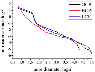
其次,按照Neimark方法检验硬化水泥浆多孔结构是否属于孔隙–固相界面分形。如图4所示,logSvs. logd的线性相关性随配合比的改变差异较大。对于普通水泥浆和石灰水泥浆,较容易分辨出三段不同的孔隙尺寸区间。对于矿渣水泥浆,不能发现独立的孔隙尺寸区间。根据Zeng等的观点,存在三类不同的孔隙区间,较大的孔隙(毛细孔),较小的孔隙(凝胶孔)及过渡孔 [10]。其中,较大的孔隙和较小的孔隙属于孔隙–固相界面分形,而过渡孔不具有分形特征。类似地,对当前的logSvs. logd曲线分区间线性拟合,结果如表2所示。由于矿渣水泥浆不存在明显的过渡孔区间,相应的线性拟合分别在logd< 1.5和logd> 1.5范围内进行。对应于普通水泥浆,矿渣水泥浆,石灰水泥浆,毛细孔的孔隙率分别为0.98%、0.78%、0.75%,因此该部分孔隙不予考虑。对于凝胶孔部分,如果确认其属于孔隙–固相界面分形,那么得到的分形维数分别为2.98、5.78、2.99,这与分形维数的一般要求相违背,即2 <DPS< 3。因此,认为硬化水泥浆多孔结构属于孔隙–固相界面分形也是不合理的。
 (a)
(a) (b)
(b)
Figure 4. Examining the property of pore surface fractal (a) 0.5 < logd < 5; (b) 0.5 < logd < 2
图4. 水泥浆多孔结构孔隙–固相界面分形检验(a) 0.5 < logd < 5;(b) 0.5< logd < 2

Table 2. The property of solid mass fractal in different pore ranges
表2. 水泥浆孔隙–固相界面分形的分区间检验
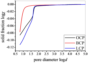
最后,按照Usteri方法检验硬化水泥浆多孔结构是否属于固相分形。如图5所示,logχvs. logd的线性相关性随配合比的改变存在一定的差异。对于普通水泥浆和石灰水泥浆,较容易分辨出两段不同的孔隙区间,小孔隙区间1 (Region 1)和大孔隙区间2 (Region 2)。对于矿渣水泥浆,则找不到明显的区间2。通过分区间线性拟合logχvs. logd的斜率,结果如表3所示。如果确认水泥浆多孔结构属于固相分形,分形维数为普通水泥浆:3 − 0.06 = 2.94 (区间1),3 − 0.22 = 2.78 (区间2);矿渣水泥浆:3 − 0.21 = 2.79;石灰水泥浆:3 − 0.09 = 2.91 (区间1),3 − 0.31 = 2.69 (区间2)。不难发现,所有的分形维数都满足一般要求2 <DSM< 3。与此同时,绝大部分的孔隙率都由分形包括,即普通水泥浆:(11.31 + 4.74)/17.94 ≈ 90%;矿渣水泥浆:14.61/16.21 ≈ 90%;石灰水泥浆:(14.64 + 6.54)/22.86 ≈ 93%。由此认为,硬化水泥浆多孔结构属于固相分形,且具有尺度依赖性,即不同的孔隙尺寸区间具有不同的固相分形维数。
 (a)
(a)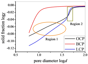 (b)
(b)
Figure 5. Examining the property of solid mass fractal (a) 0.5 < logd < 5; (b) 0.5 < logd < 2
图5. 水泥浆多孔结构固相分形检验(a) 0.5 < logd < 5;(b) 0.5 < logd < 2

Table 3. The property of solid mass fractal in different pore ranges
表3. 水泥浆固相分形的分区间检验
4. 分形模型
如图6所示,固相分形通过迭代的一般方法来构造,包含孔隙相和迭代相 [14] [15] [16] [17] [18]。具体而言,先在E维空间中定义边长为L的空白区域,该区域进一步分成N=nE的小空白区域,正整数n表示每个维度上的小空白区域数目。基本迭代结构由变量w和b所决定,即每次迭代过程迭代相所占的比例和数目,满足关系b=wN。迭代过程作用于迭代相。随着迭代步骤的进行,孔隙相逐渐增多,迭代相逐渐减少。连续迭代过程所构造的多孔结构性质如下所述。
第一步:尺寸为a1=L/n的迭代相和孔隙相数目分别为wN和(1 −w)N。
第二步:尺寸为a2=L/n2的迭代相和孔隙相数目分别为(wN)2和(1 −w)wN2。
第i步:尺寸为ai=L/ni的迭代相和孔隙相数目分别为(wN)i和(1 −w)Niw(i−1)。
根据式(6)的定义,经过i次迭代步骤之后,多孔结构的密实度为χi=wi。如果定义常数D= log(Nw)/log(n),再代入关系式ai=L/ni和N=nE,那么多孔结构的密实度χi满足
(8)
按照式(7)的定义,式(8)表示的是迭代过程所构造的多孔结构属于E维空间的固相分形,且其分形维数为D。
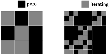
Figure 6. Schematic illustration of the solid mass fractal model withE= 2,n= 3, andb= 5
图6. 固相分形构造的一般迭代方法示意图,n= 3,E= 2,b= 5
5. 案例分析
配制三组不同水灰比(0.4, 0.5, 0.6)的普通硬化水泥浆,其龄期一致为28天。成型后,水泥浆试块放置在95% ± 10%相对湿度,20˚C ± 1˚C温度的环境中。养护后,水泥浆试块切成小块放入烘箱干燥再进行压汞测试,结果如图7所示。类似地,首先将密实度与孔隙尺寸在对数坐标系logχvs. logd画出。如图8所示,基于线性相关性,将logχvs. logd分为两个区间,即小孔隙区间和大孔隙区间。定义dupp和dlow分别为孔隙尺寸的上限和下限,dthr为临界孔隙尺寸。由图8可知,dlow= 0.004 μm,dthr= 0.1 μm,dupp= 2 μm。换言之,小孔隙区间为dthr~dlow,即0.1~0.004 μm;大孔隙区间为dupp~dthr,即2~0.1 μm。小孔隙区间对应凝胶孔,大孔隙区间对应毛细孔。通过分区间线性拟合,计算出相应的斜率值(kup,klow)。对于E=3维空间,大孔隙区间和小孔隙区间的固相分形维数(Dupp,Dlow)满足Dupp= 3 −kupp,Dlow= 3 −klow。计算结果如表4所示,其中(fupp,flow)表示大孔隙区间和小孔隙区间相应的孔隙率。
根据固相分形模型,硬化水泥浆的多孔结构模拟分为两部分。对于大孔隙区间dupp~dthr,分形模型中的参数i,n由iupp,nupp代替,满足iupp= log(dupp/dthr)/log(nupp)及nupp≥ 2,iupp≥ 2,nupp.^Dupp≥ 1。文中符号.^表示幂运算。迭代相所占的比例和数目通过log(wupp) = (Dupp− 3)∙log(nupp),bupp=wupp∙(nupp)3得到。本征孔隙率
= 1 − [bupp/(nupp)3].^iupp。对于小孔隙区间dthr~dlow,分形模型中的参数i,n由ilow,nlow代替,满足ilow= log(dthr/dlow)/log(nlow)及nlow≥ 2,ilow≥ 2,nlow.^Dlow≥ 1。迭代相所占的比例和数目通过log(wlow) = (Dlow− 3)∙log(nlow),blow=wlow∙(nlow)3得到。本征孔隙率
= 1 − [blow/(nlow)3].^ilow。
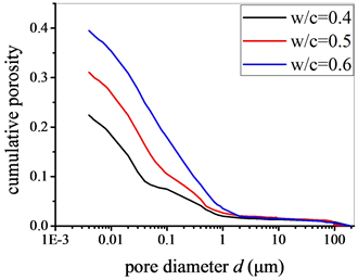
Figure 7. MIP test data of ordinary cement pastes with varying w/c ratios
图7. 不同水灰比普通硬化水泥浆压汞测试曲线
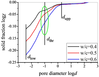
Figure 8. The property of solid mass fractal for ordinary cement pastes with varying w/c ratios
图8. 不同水灰比普通硬化水泥浆固相分形检验

Table 4. Structural parameters of ordinary cement pastes with varying w/c ratios
表4. 不同水灰比普通水泥浆多孔结构参数
硬化水泥浆多孔结构的固相分形模拟按照孔隙尺寸从大到小进行。首先经过iupp次迭代生成大孔隙结构,此时迭代相的尺寸,数目分别为dthr,(bupp).^iupp。然后经过ilow次迭代生成小孔隙结构。在此过程中,并不是所有尺寸为dthr的迭代相继续进行迭代过程。定义尺寸为dthr的迭代相继续进行迭代过程的比例为γ(γ≤ 1),该部分为凝胶相。另外比例为(1 −γ)的迭代相不再继续进行迭代过程,该部分为固相。按照这种方法,最终构造的多孔结构孔隙率表示为
。同时,孔隙尺寸分布满足
如果
;
如果
。
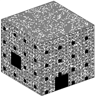
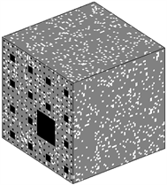
按照上述方法计算出当前不同水灰比普通硬化水泥浆固相分形模拟的相关参数,如表5所示。固相分形模拟的普通硬化水泥浆多孔结构如图9~11所示。其中,迭代相,孔隙相及固相成分在给定结构参数的前提下在模拟空间随机分布。众所周知,压汞实验提供的是压入量与施压力之间的关系。利用本文提出的固相分形模型,可实现对水泥浆多孔结构的三维直观展示。另外,结合模拟得到的三维多孔结构与有限元、格子玻尔兹曼方法等数值算法可进一步探讨水泥浆的基本物理、力学性质。图12所示为固相分形模拟的孔隙尺寸分布与压汞实验测试的比较,二者符合较好。

Table 5. Parameters of solid mass fractal model of ordinary cement pastes with varying w/c ratios
表5. 不同水灰比普通水泥浆固相分形模拟参数
 (a)
(a) (b)
(b)
Figure 9. Modeled pore structure of ordinary cement paste with w/c of 0.4 and curing age of 28 d (a) capillary pores; (b) C-S-H gel pores, where white denotes solid component
图9. 水灰比为0.4养护28天的普通水泥浆固相分形结构(a) 毛细孔;(b) 凝胶孔,白色代表固相
 (a)
(a) (b)
(b)
Figure 10. Modeled pore structure of ordinary cement paste with w/c of 0.5 and curing age of 28 d (a) capillary pores; (b) C-S-H gel pores, where white denotes solid component
图10. 水灰比为0.5养护28天的普通水泥浆固相分形结构(a) 毛细孔;(b) 凝胶孔,白色代表固相
 (a)
(a) (b)
(b)
Figure 11. Modeled pore structure of ordinary cement paste with w/c of 0.6 and curing age of 28 d (a) capillary pores; (b) C-S-H gel pores, where white denotes solid component
图11. 水灰比为0.6养护28天的普通水泥浆固相分形结构(a) 毛细孔;(b) 凝胶孔,白色代表固相
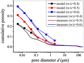
Figure 12. Comparison of pore size distribution between measure and model
图12. 孔隙尺寸分布实验与模拟对比
6. 结论
本文基于压汞实验探讨了水泥基材料多孔结构的分形特征,获得主要结论如下:
1) 水泥基材料多孔结构具有固相分形特征,且具有尺度依赖性。
2) 基于固相分形的一般构造方法,硬化水泥浆多孔结构的模拟按照孔隙尺寸从大(毛细孔)到小(凝胶孔)逐级进行。
致谢
本文研究工作受到苏州轨道交通6号线土建01标科研配套资金的资助。
NOTES
*通讯作者。